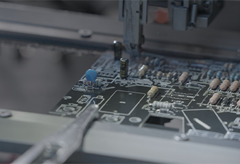
SMT machine places small electronic components (such as capacitors, inductors, diodes, MOSFETs) onto PCB pads pre-coated with solder paste.
Step 2
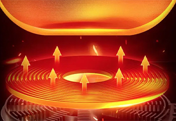
SMT components are heated in a reflow oven, melting the solder paste and bonding the components to the PCB.
Step 2
SMT components are heated in a reflow oven, melting the solder paste and bonding the components to the PCB.
Step 3
Through-hole components (e.g., power connectors, pins) are soldered using wave soldering or hand soldering tools.
Step 4
After all components are installed and soldered, AOI (Automated Optical Inspection) is used to detect issues like incorrect placement, polarity, or soldering defects (e.g., cold solder joints, bridging).
Step 4
After all components are installed and soldered, AOI (Automated Optical Inspection) is used to detect issues like incorrect placement, polarity, or soldering defects (e.g., cold solder joints, bridging).
Step 5
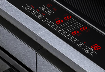
Use an electronic load tester to verify that the PCB’s output voltage and current meet design specifications.
Step 6
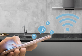
Use ATE (Automated Test Equipment) to test electrical functions, withstand voltage, and ensure the PCB performs reliably.
Step 6
Use ATE (Automated Test Equipment) to test electrical functions, withstand voltage, and ensure the PCB performs reliably.


